
Metrology and inspection
Shared measurement, calibration, incoming inspection, nonconformance control and evidence records support every laboratory.
Long-term facility / Functional program defined
A phased engineering, laboratory, prototype, verification and lifecycle environment specified around HST deliverables.
Long-term facility goalLong-term facility / Interactive pilot
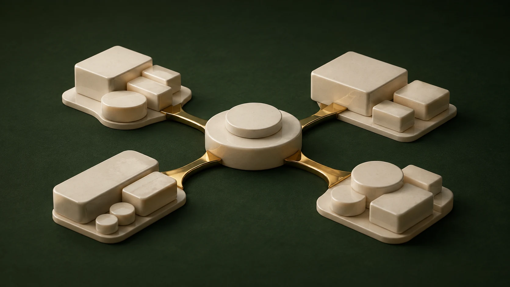
Numbers connect each volume to its planned function. Gold paths indicate the exchange of design records, hardware and evidence. No site, scale or building layout has been selected.
Phase 1
Requirements, CAD, BOMs, simulation and configuration control. Shared technical records connect design decisions to laboratory and prototype evidence.
01 / Technical scope
The facility program defines the functions, evidence flow and phased capacity required to move HST from controlled engineering data to verified subsystems.
The long-term goal is to bring design, laboratory work, prototyping and lifecycle support into one coordinated R&D environment. Shared or partner facilities could support early work before a dedicated site is justified.
No location, building design, equipment purchase or construction budget has been selected. The illustration shows only a high-level spatial idea.
02 / Shared technical controls
Shared measurement, calibration, incoming inspection, nonconformance control and evidence records support every laboratory.
Shared safety, instrumented testing, data capture, acceptance decisions, fault isolation and baseline feedback.
Material handling, electronics, fluid systems, soft surfaces, assembly and test require different contamination and safety controls.
Phase 1 supports systems engineering, secure configuration control, CAD and BOM development, simulation, electronics and controls benches, dimensional metrology and bounded prototype work. It can begin without a full integration hall.
Initial computing, software, bench and safe prototype-space requirements follow the current CAD, BOM, interface and analysis workload.
Phase 2 adds dedicated structure and motion, power and thermal, sensing and surface, artificial-physiology, controls and human-factors laboratories. Their equipment, throughput and verification plans follow named work packages and technical risks.
Shared metrology and calibration establish whether measurements are trustworthy. Configuration control identifies the evaluated design; data systems preserve raw results, processing history and review decisions. Safety engineering, equipment maintenance, environmental monitoring, cybersecurity and failure analysis support every workstream.
Design and configuration work needs secure data and review space. Fabrication needs material, extraction and machine controls. Electronics, optics, fluids, soft surfaces and mechanical assemblies impose different cleanliness and contamination requirements.
Receiving, inspection, quarantine, laboratory work, assembly, verification and accepted storage require deliberate routes so unverified material cannot enter a released configuration unnoticed.
A credible equipment list begins with the CAD, analysis, prototype and verification work scheduled for each phase. It identifies required accuracy, working envelope, utilization, staffing, calibration, utilities, consumables and maintenance.
This avoids purchasing an impressive general laboratory that does not match the program’s actual bottlenecks. Expansion is justified by workload and evidence demand.
Phase 3 adds configuration-controlled subsystem assembly and integration areas, inspection hold points, test cells, quarantine and failure-analysis capability. Incoming items require identification and inspection status; build stations require released work instructions and known tooling; test cells require approved configurations, instrumentation and acceptance criteria.
Nonconforming hardware is isolated, investigated and dispositioned before it can progress. The resulting evidence returns to both the individual build record and the controlled design baseline.
Phase 4 establishes lifecycle service, repair, replacement and renewal research. It would maintain as-built and as-serviced records for each future body.
Repair and replacement procedures require their own validation and return-to-service criteria.